Interactive Control Systems Tools
Control systems analysis
Analysis of a 2-nd order systems (time domain)
Step response of a second order systems
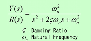
The transfer function of a 2-nd order system is generally represented by the following transfer function:

The dynamic behavior of the second-order system can then be described in terms of two parameters: the damping ratio and the natural frequency.
If the dumping ratio is between 0 and 1, the system poles are complex conjugates and lie in the left-half s plane. The system is then called underdamped, and the transient response is oscillatory. If the damping ratio is equal to 1 the system is called critically damped, and when the damping ratio is larger than 1 we have overdamped system. The transient response of critically damped and overdamped systems do not oscillate. If the damping ratio is 0, the transient response does not die out.
Depending on the values of the damping ratio the equations describing the system response have the following forms:
(1) Underdamped system

(2) Critically damped system
![]()
(3) Overdamped system

(4) Undamped system
![]()
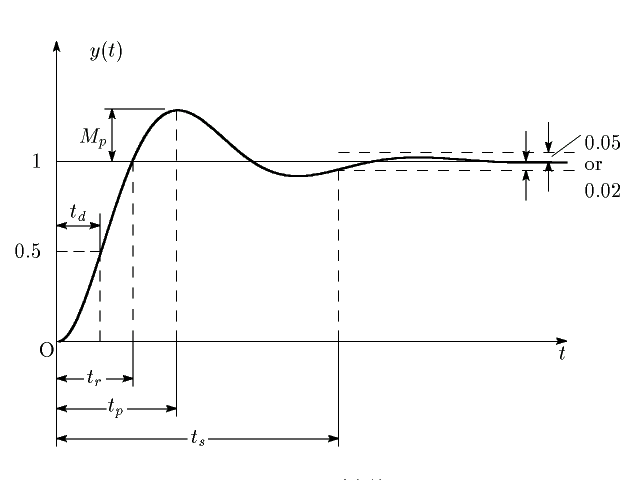
Definitions of transient-response specifications
In many practical cases, the desired performance characteristics of control systems are specified in terms of time domain quantities. Systems with energy storage cannot respond instantaneously and will exhibit transient responses whenever they are subjected to inputs or disturbances.
Frequently, the performance characteristics of a control system are specified in terms of the transient response to a unit-step input since it is easy to generate and is sufficiently drastic. (If the response to a step input is known, it is mathematically possible to compute the response to any input).
The transient response of a system to a unit-step input depends on the initial conditions, but for convenience in comparing the transient-responses of various systems, it is common practice to use zero initial conditions. In specifying the transient-response characteristics of a control system to a unit-step input, it is common to specify the following:

